
Another FrankenBurner
-
Posts
625 -
Joined
-
Last visited
Content Type
Profiles
Forums
Articles
Gallery
Downloads
Events
Posts posted by Another FrankenBurner
-
-
I have worked with burner systems which employ a similar high/low or on/bypass system. I overlooked the idea for forge application. Thank you for pointing it out. It is a simpler method than the modulating valve and all the things they require.
-
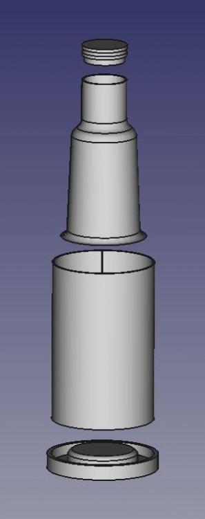
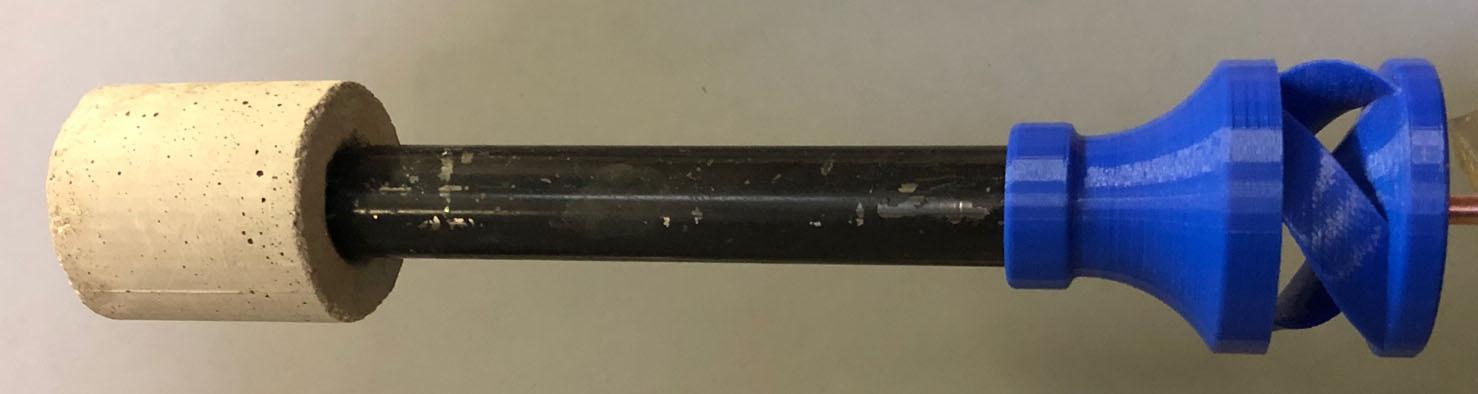
More experiments are needed with the refractory nozzles. I very much like them. Here's one reason why:
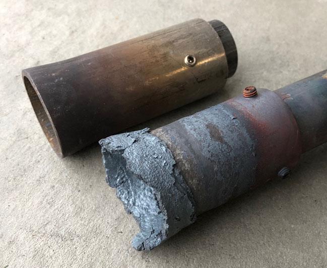
These are even the fancier 316 stainless. The wall thickness is now very thin for most of it's length.
-
Thanks guys. Technology is great, when it works.
As to purchasing a controller, if you search Amazon for a "ramp soak temperature controller," there are several for under $100. Look for one with PID control and SSR output. If you just want PID temperature control minus the ramp soak, you can get one for around $30. On Ebay, I see them as low as $12.
I had wondered about controlling the fuel output in a forge. You could on/off the fuel but if the burner could handle lower pressures, a Maxitrol Modulator valve could be used with the proper controller to really dial the temperature in. As far as I know, this would require an exotic thermocouple type to measure temperatures above 2200°F.
I previously mentioned that I purchased some generic tweco 14T-30 mig tips which run a 1/2 inch burner rich compared to the standard Miller 030 tip. For a minute I thought I had missed the big picture with these burners. Then I put the Miller 030 tip in and the burner runs beautifully again. I measured the tips to see why. The Miller 030 tip is at 0.037 and the generic tweco is at 0.039. Two thousandths and a poor running burner. If you are having a problem with a burner but you suspect the mig tip size is close, try another brand. Now I want to measure several tips to see if same brand tips vary in size per batch. If the variances are great enough, I may eventually abandon mig tips for capillary tubing or needle stock.
An update on the 450 in3 forge, it likes 4 psi to heat for forge work, a nice high orange. Also, the idle setting to maintain temperature, on these burners is very low and the forge goes quiet. It is a bit on the large side but it is great to work with.
-
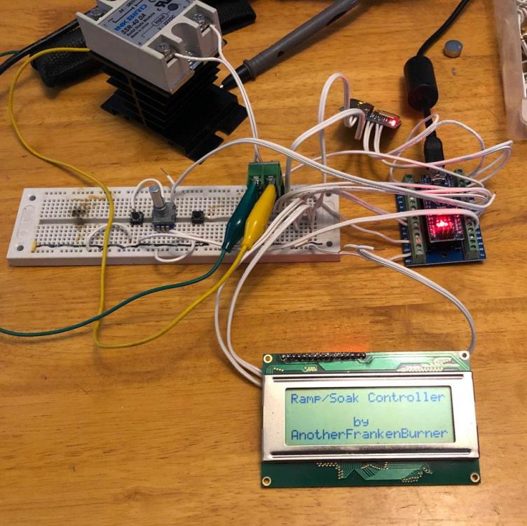
The controller ran for the first time today. It is still on the breadboard but it reads the thermocouple, it cycles the heat relay, and it reads the schedules off of an SD card.
-
Thank you for the kind words Mikey. They are encouraging.
We attempted another cast today. This was a gravity only experiment. The surface texture is rougher. Some of the investment showed full detail which was not in the cast. The porosity is much less and the cast is more complete.
Here it is hot out of the flask:
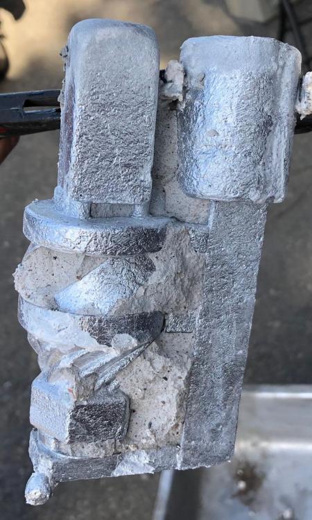
We like what the vacuum does for us and will continue to experiment. We are still experimenting with investment as well.
I am also building an Arduino based ramp/soak temperature controller. I have some code work to do. We currently manually control the cycles which is tedious and we are not ramping the temperature properly. The casting process will be much easier on us so experiments will be more often. The flasks will not be thermally shocked which will hopefully increase the success rate.
I had ordered some generic tweco 14T-30 mig tips. The flame shows much more green/rich then some Miller standard 030 tips. It makes me wonder if the jet is larger and delivering more fuel or if it is a change in mixing due to a different fuel stream shape. I am going to put a flow meter inline to compare. Not all mig tips are created equal.
-
17 hours ago, jwmelvin said:
I don’t think there is so much risk
Deep fryers contain risk. Gas heated deep fryers contain more risk. You are heating a large quantity of oil in close proximity to flames. If heated to high enough temperatures, oil is happy to become a fuel.
Deep fryers need control systems. Basic commercial gas deep fryers have a pilot flame safety thermopile, a pilot safety dual gas valve, an easily accessible manual gas shutoff valve, a thermostat with a maximum of 400°F, and a high limit thermostat which triggers at 450°F. In commercial kitchens around here, they are also required to have fire resistant surroundings, an exhaust hood, and an ansul system which is an automatic fire suppression and gas disconnect system. Even with all this, I have responded to several fryer fire calls. Some of which damaged the building.
If you skip the controls for manual monitoring and control, there is even more risk.
As to type of burners, most basic commercial models have 3 or 4 cast iron NARBs which send the flames into heat exchanger tubes with baffles and up a flue. Natural gas in commercial kitchens runs very low pressures, the burner manifold pressure is usually 3.5 inch wc (0.126 psi). To get the btu's needed, burner tubes have to be designed for the low pressure and employ large gas orifices(comparatively).
The flames impinge on the welds at the front of the heat exchanger tubes which often crack and oil leaks into the flame. My company will not fix these welds(even though it would be easy) because we don't want to be liable. Too much risk.
If you need a visual demonstration, do an internet search for "dangers of deep frying."
Small electric deep fryers are fairly inexpensive.
-
I will work on better pictures. I like evaluations and any extra information.
-
This evenings pour was a complete failure and disappointment. For the first 30 seconds, it was beautiful. Then the mold blew out due to vacuum again and filled the safety reservoir and molten aluminum headed down the vacuum tube towards the pump. It filled fittings. Luckily, it was stopped by a screen. We will be using a larger safety reservoir and have an inline filter from now on. We learned a lot and have several ideas to play with for the next pours.
3 hours ago, D.Rotblatt said:Just a question to ponder or experiment with.
It sure is. I will be experimenting. I have a few NARB and other ideas to play with. It sounds like Frosty will be trying one with his NARBs as well.
3 hours ago, D.Rotblatt said:Curious, did you design these to allow for a damper or baffle of some sort to change the flame to a more reducing flame?
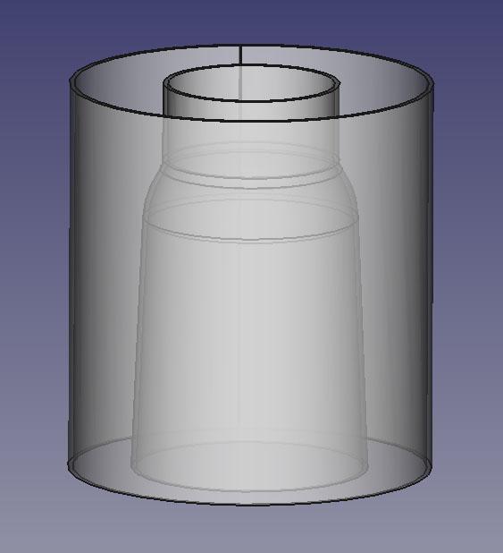
Yes. There are two true round sections so that it can use a sliding choke like on your hybrid style burner. If you look back into the first pages, there are some images of prototypes with chokes. Once we have the casting process figured out a little better, I am going to change the model so the OD matches the ID of some readily available pipe or tubing.
Also, I have run the latest versions with my pressure gauge resting on the minimum peg without huffing or going rich.
47 minutes ago, Lou L said:I have nothing intelligent to add to this thread. It is amazing.
Thank you sir. Science and fire, how could it not be fun to tinker with? As far as a book, most of those details are in this thread, on this awesome forum. As to monetization, that was never the original intent. I just wanted to tinker with burners and hopefully end up with some hot ones for my forges. Others have stated they want some too, so now we are going to try to supply them.
-
Congrats u_p_country. It's a great thing when the burner works after all that work.
In order to get decent pictures, I have to be in a medium-low light, focus directly on the flame and sometimes lower the exposure on my camera.
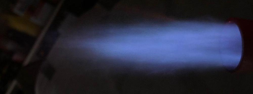
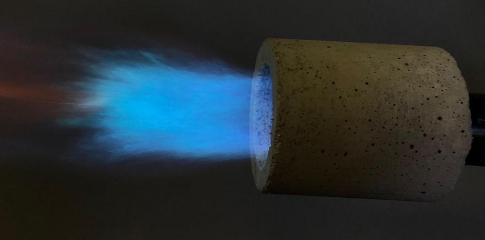
Speaking of pictures, here you go Mikey. These are a 1.5 inch stainless nozzle on one of my 1/2 mix tube burners. Sorry about the background clutter.
This picture shows the true nozzle temperature/color on the outside:
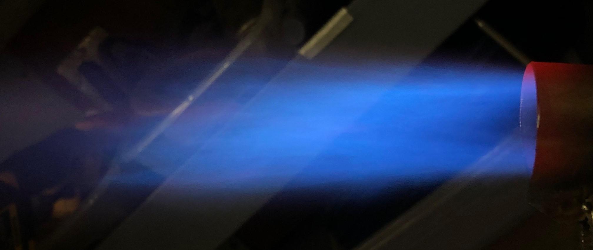
Here is the same flame with the camera exposure lowered to see the flame:

I am now using refractory nozzles only.
-
Yes, there are feeders into the tops from the main sprue. I had mentioned what you said about the ribs freezing first and my father added those feeders. Also, oversized sprue and risers for the large liquid mass to pull from. We are feeding to the bottom of the lower reducer so we may need to add blind risers if we still see porosity at the top of the reducer.
I follow the NARB thread, I have kept up on your 1/8 inch NARB. It looks great. I want to play with NARBs just because I am the tinkering type and have some ideas which will drive me crazy until I have tested them.
As to the inducers usefulness in the NARB, I think it could be a good carburetor. As a tube burner, it induces more air and mixes better then any of the other styles I have played with. When playing with different nozzle shapes and sizes, it can usually be tuned to burn clean. Hopefully that holds true when it is faced with a NARB.
-
Thanks guys. They are hot indeed. We now have a few kast o lite nozzles working. We 3D printed forms for the big forge so the nozzles are kast o lite and cast directly in the wall of the forge. We have not had any problems but they have not been in service long.
I am now playing with reusable printed forms for the nozzle design experiments.
What I am more excited about, I am starting to play with NARB design.
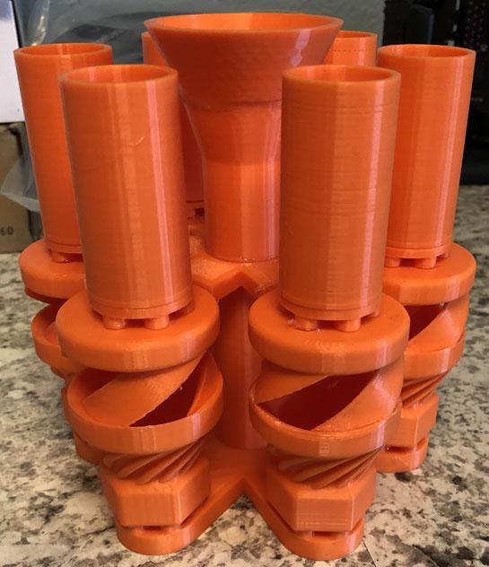
My father had an idea for a feed system which he cad, printed, assembled, and it is now in investment for a pour tomorrow. We are attempting 6 in one pour. Fingers crossed.
-
Burner 1 reminds me of a Z burner by Larry Zoeller.
One thing to pay attention to is what you are seeing with your eyes. All of the advice given here will be based on the pictures and the camera can skew the flame enough to look completely different then it is in reality. I have also noticed that depending on the ambient lighting, the flame can present itself completely differently.
Mikey has been good about explaining reading the flame. It is the most important thing I have learned, from this forum, when it comes to tinkering with burners. We almost need a Flame 101 pdf on the forum. Without knowing what you are looking at or for, how can you tune a burner?
That said, many varieties of flame are useful and desirable. Many people prefer a reducing/rich flame as a means to limit scale production. This conversation is explaining a neutral flame and not a flame you have to achieve. A lot of burners are not capable of it. My main forge runs a flame which is very rich and it still gets the job done at a cost of fuel.
Lets focus on the first picture. It looks to be running rich(according to the picture). It shows 4 clearly separate zones and so it is a nice picture to talk about.
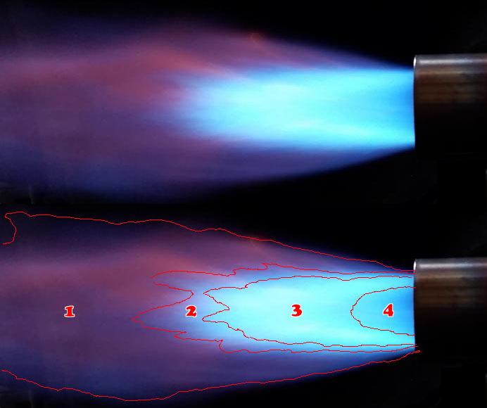
Zone 1 is what a lot of people call the secondary or tertiary flame. I like tertiary flame because secondary gets confusing, you will see why in a minute. Anyway, we want as little of this as possible. None visible, in a perfect world.
Zone 2 is sometimes referred to as the primary or secondary envelope. Take a good look at it's color because that is what you want the entire flame to look like in a perfect world. It is the flame which is mixed and burning properly.
Zone 3 is sometimes referred to as the primary or secondary envelope. It has a green quality to it. This is an indication of a rich flame. In the perfect world flame, zone 2 and zone 3 will be one zone of a uniform color.
Zone 4, I'm not sure what it is referenced as. We want him to look hollow or void. Transparent.
Here is the best example picture I have:
If the flame goes dark blue or even to levels of purple, it is oxidizing:
Now hopefully Mikey will chime in and add details.
-
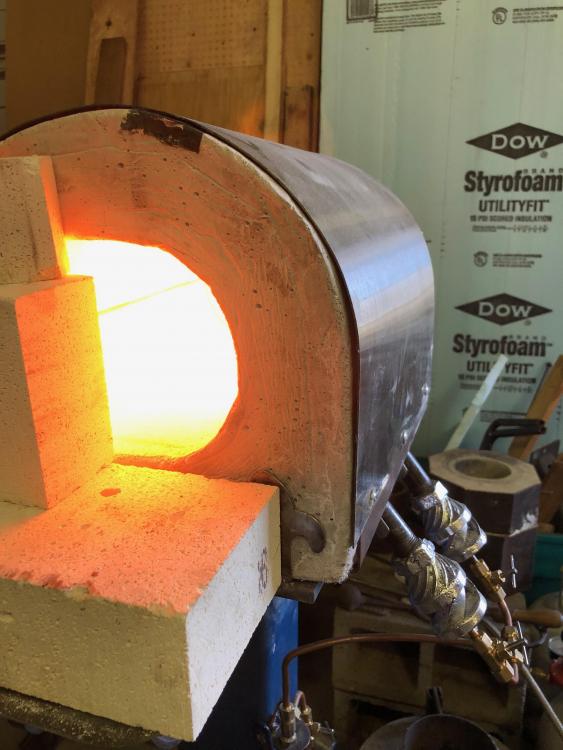
We were excited to finally put something to a forge to see the end results of all the work. We built that forge large to test the 1/2" burners. I don't remember but I am wanting to say it is in the 450 in3 ball park. We are happy with the performance. The 1/2" burners are nice in that they are so small and their output is high enough for what we are doing with them.
My daily driver is a refrigerant jug forge(150 in3) with a top mounted 3/4" modified sidearm burner. The sidearm burner is huge and sticks out like a large arm which sometimes becomes a moment arm. It runs rich enough to show green and has to be turned up enough to cause dragons breath to get to forging temps. I will be putting one of the 1/2" guys into it to see the changes. I am hoping for and expecting fuel savings. These new burners are happy to burn clean in a variety of configurations with some tuning. They can also be turned down very low which will be nice for the idle circuit. With the sidearm, the idle setting had to be set high to prevent the burner from huffing.
I have been playing with nozzle design lately. I am up to v4 on the nozzles. I want to understand the dynamics of stepped, tapered, and stepped tapered. This includes playing with the harshness of the step, the angle of the taper, and the length of the nozzle. I also want to understand what happens when the nozzle outlet size is much larger then usual, what the pros/cons are, how large is too large, and why. We are happy with the kastolite nozzles. They can be shaped however desired, they don't oxidize, and they don't transfer as much heat to the mix tube.
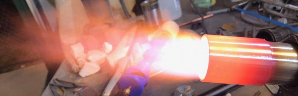
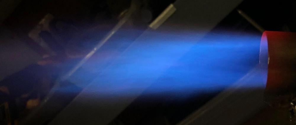
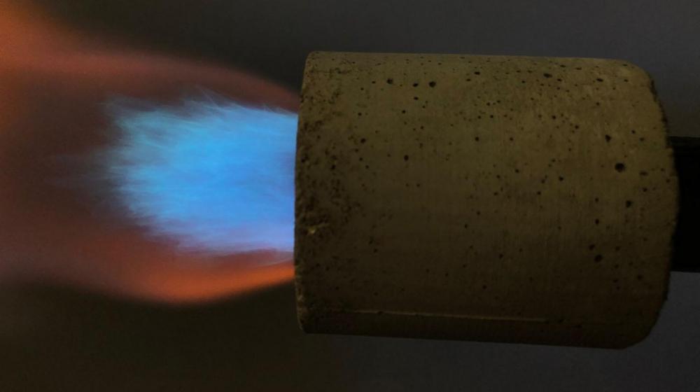
Here is a half inch burner with a 1.5 inch stainless experiment nozzle:

It will heat. I reduced the exposure so the flame could be seen and look at that beautiful blue:

At the other end of the nozzle size spectrum, we held the 3/4 burner to the cast nozzles of the big forge. The nozzles were smaller sized(1.25 outlet) for the 1/2" burners. Here is that flame with a cold forge:
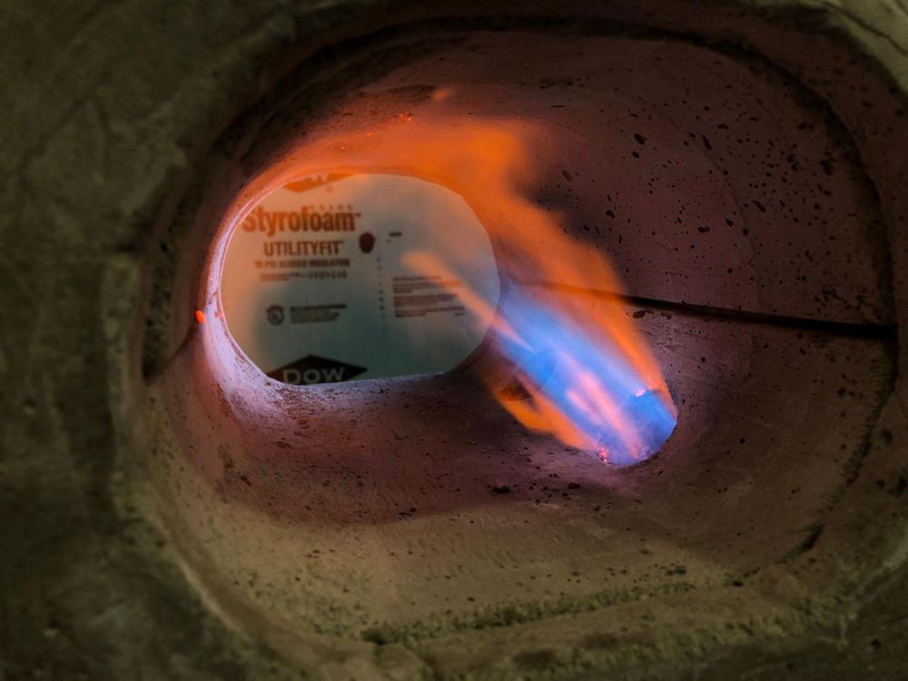
We didn't have the mix tube aligned with the nozzle very well. The nozzles point more towards the ceiling then that flame is. The kastolite is fresh and that is what is causing the contrasting orange.
-
We took a couple of the inducers from the last rough pour and pointed them at a forge.
-
D.Rotblatt talks about the zircon/adbond coating in this thread:
He states that using fumed silica to make colloidal silica works well as a rigidizer, but it does not work when mixed with zircopax to make a finish coat. He uses adbond II for the finish coating.
-
Based on what you said, I know we did it wrong. We are changing the feed system. I suspect you are exactly correct about what I am seeing. Sprued from one end and the ribs freezing before the lower portion would explain where I am seeing the porosity problems.
-
I'm glad you both like them. It is exciting. I think I have the inducer ratio's tuned in to a point I am happy. I have scaled to the 3/8" and the 3/4" with the exact same ratios and they both do very well. More air can be induced but then the mix tube velocity starts to scream and the induction volume and fuel volume curves don't match as well. I think I have found a nice balance for a stable, well ranged, versatile burner.
The gentle nudges in Burners 101 were not lost on me, I will be scaling to the 1/4", just for Mikey. I will have to change up the jet assembly for that small.
I am also starting to tinker in the NARB side of things. I am as excited about playing with NARBs as I was about playing with inducers. I know almost nothing about their dynamics and look forward to becoming acquainted.
Catchy name? I kind of like Frosty's "Twisted Gizmo." Others have referred to them as vortex injectors or vortex inducers. I'm up for suggestions, I didn't put much mind to it.
We are getting close to aluminum inducers. A few poured yesterday are now functioning burners. Just ugly. One total failure is now a burner shaped candle holder. Big flames coming out of that one.
I don't have any pictures of the sprues and the porosity problems currently, but I will get some. I appreciate the help. We are going to get some proper investment so that we can know how it functions and what we are aiming for with the DIY investment experiments.
-
I am thankful for the safety first concerns of the folks on these threads. It's a dangerous hobby.
-
I hadn't even thought about that Frosty. Modern refrigerants are not CFC's, phaseout in 1996. HCFC's are in the process of being phased out, 90% phaseout in 2015, full phaseout in 2020. If you are wanting to stay away from chlorine, you could get an evacuated cylinder from an HFC. R134a(blue), R404a(orange), or R410a(pink) are the common ones. R410a is higher pressure so the cylinders may be thicker walled but I am not positive on that. I will still use the same safety precautions with these cylinders.
-
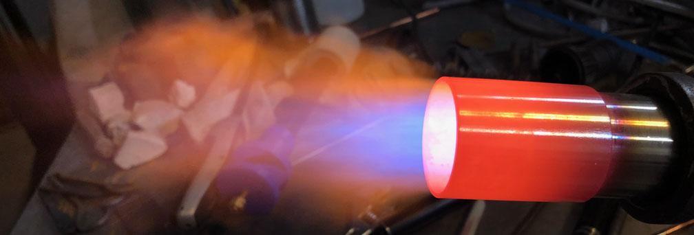
Another fun Saturday. We finally played with the 3/4 burner. He ended up getting the 045 jet. This flame is at 4 psi and the nozzle ends at 1.5 inch. It's a big slow flame. The orange is from the kast o lite nozzle.
.
Here is 10 psi:
Here is the 3/4 guy:

It still needs some tinkering, more nozzle experiments, and the mix tube is too long. When the nozzle matches the inducer, the final FAM stream is slowed, the jet size is increased, and the induction volume curve matches the fuel volume curve through fuel pressure range. We 3D printed a thin form for the kast o lite to make this nozzle. A 1:12 taper after a step.
We made 4 more flasks and 3D printed bottoms which include the funnel/sprues for the inducer.

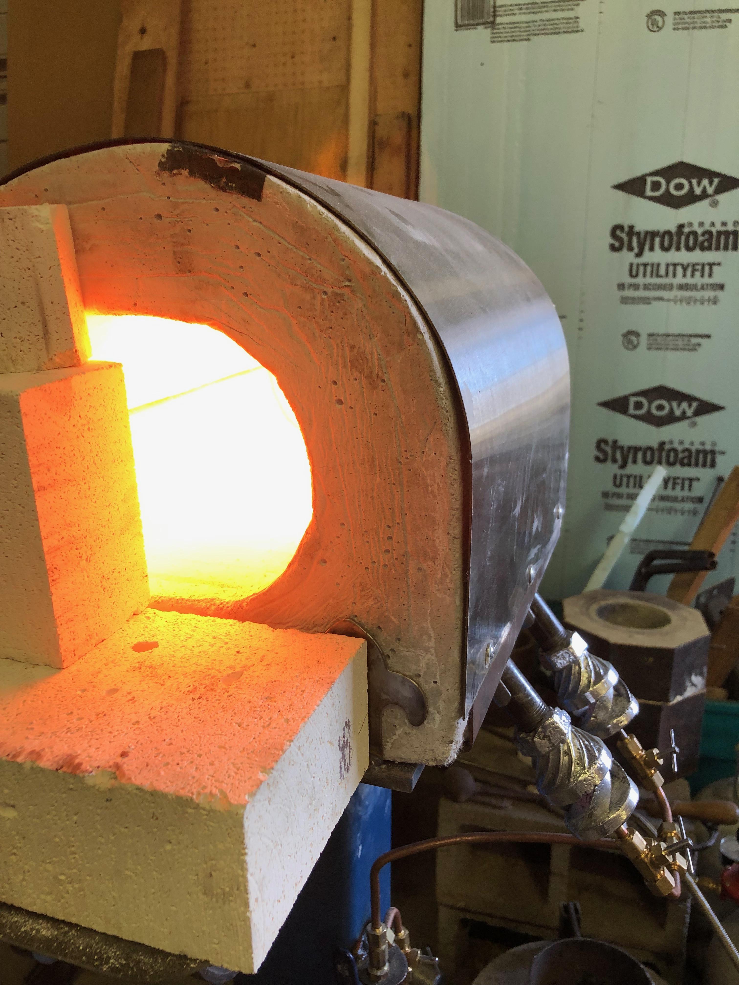
We had obtained a dilapidated larger kiln and rebuilt it, so today we poured 5 experimental investment mix flasks. We ran the furnace with the ugly salvaged 1/2 inch burner from the last pour. We are happy with how it runs.
.thumb.JPG.b26456b94fc3715d75610255b058fca7.JPG)
We have pulled out working burners but they are not good enough yet. Investment still needs work. The burners have porosity problems. A good learning day.
-
5 hours ago, Frosty said:
Isn't there an opening size under which a flame can't propagate?
Isn't that a function of final FAM velocity? I have seen commercial gunned ribbon burners with very small ports(1/32 of an inch) which flash into the plenum if the fan doesn't run.
-
While I am not advising anyone of anything here, especially not burning refrigerant and huffing it, some of the folks in the HVAC profession have burned lots of refrigerant and "manned" through it to finish the job. I personally know a couple of those... people and they are still with us. I had studied burned refrigerant, worried of killing myself at work. It sounds like it is highly unlikely that phosgene gas will be produced by burning refrigerant. The article stated that hydrofluoric acid and if the refrigerant contains chlorine, hydrochloric acid are what give the unpleasant breath. Along with a host of other nasties. I had also read that phosgene has a sweet, not unpleasant odor and that if you get enough of a dose to smell it, get your affairs in order. I don't know how much of it is true though, it is hard to wade through the old wives tales and find a definitive answer. I avoid it through proper practices. I always blow the cans out with air and make the initial cuts outside. Though, as Charles R. Stevens stated, if you want complete avoidance, the disposable helium cans are pretty much the same thing.
When it comes to safety, over reacting is better then under reacting.
-
A mowed lawn... You know, I don't remember. It has been a long while since I have accidentally burned refrigerant. It is unpleasant enough that you immediately know to stop what you are doing and leave the area. The air blown through the can seems to take care of it though. I use the jugs for lots of stuff and have cut open dozens of them.
-
I was aware of the machinable wax filament. I have read it is difficult to use. I would have to change the firmware on my machine to lower the minimum print temperature, convert to a direct extruder system instead of the Bowden system and it sounds like a fight with bed adhesion. I might look into another machine as I still like the idea of using it.
I had thought to do a silicone mold to make wax forms but I didn't think I could with this design. I don't know much about silicone molds. There is a large void in the middle of the inducers so I don't know how I would get the print and the waxes out of the mold. I would like to figure it out so that I don't have to reprint it each time but can't think of how to do it.
I don't suspect the investment is cracking due to expansion. Once we started using the flask, the cast comes out of burnout without cracks. The last one was cracked by the vacuum I suspect. We are tinkerers and so we are still playing with DIY investments which is probably the problem. We are also messing with the burnout schedule. When we are tired of failing, we will get some proper investment and follow it's instructions.
I don't think we are sucking investment into the print like I originally worried about. To test though, we have an investment made which we pulled a deep vacuum on for several minutes. We are going to burn it out and break the mold apart to see if there is any evidence of it. I do like the idea of using shellac to smooth the print though. The shellac will burnout ok without adding problems?
Thank you for the casting advice. It is fun stuff. Our favorite part is the moment of truth. All that work buried in an investment and you don't know if it was successful.
We now have a larger kiln and several flasks made up so we can start doing multiple experiments in one go. That should speed things up.


.JPG.12573483644e933d90a5f5610c0cbd89.JPG)
Burners 101
in Gas Forges
Posted
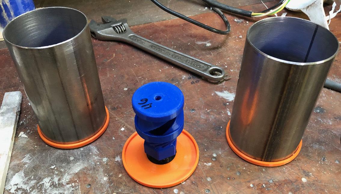
Now you are just cheating. Stepping away from thick walled iron pipe nominal sizing. What if people want to hang their body weight from the burner sticking out of the side of the forge? Maybe hang a hammer/tong rack from the burner tube?
Why not push further? Currently on Amazon, for $11, you can get a 12 inch length of 1 inch OD, 0.93 ID tubing in 316 stainless. (Search for "stainless tubing") Almost in 1 inch pipe ID territory.
Higher volume, lower velocity. A slower shorter flame. If enough extra air is induced, a larger jet for higher output.
There will be less mass to conduct heat away from the business end is the only maybe downside I can see. I am using refractory nozzles so it has not been a problem.
I am sticking with normal pipe sizes for the inducer heads because people like to use pipe and build their own thing. I have been playing with thin wall pipe/tube for my own personal burners.