
Another FrankenBurner
-
Posts
625 -
Joined
-
Last visited
Content Type
Profiles
Forums
Articles
Gallery
Downloads
Events
Posts posted by Another FrankenBurner
-
-
The angle I am talking about is the chord line in relation to the axis. Does that make sense?
-
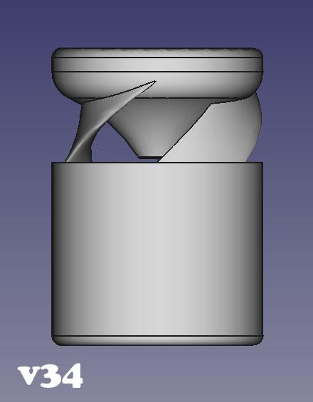
At this point I am changing the angle of ribs in relation to the jet to see what does best. My initial suspicions are that close to 90° starts to defeat the point in airfoil at all, close to 0° is a paddle which gets in the way vorticial flow. Version 34 happened to be at 75°.
-
The 3/4 inch modified sidearm burner in my refrigerant jug forge has an 035 tip running at 5 psi and it runs for a long time on a 5 gallon tank. It runs quite rich and is too big so I have nice blue dragons breath. V34 uses an 030 tip and the same size nozzle with a smaller slower neutral flame. I am hoping for fuel savings.
As to the profile, a picture would be great. Hand drawn is fine as well. I had a few curved airfoils to match the radius but they all had turbulence in the lower curve. I don't know much about airfoils so I most likely did them wrong. Also, because the air induces in straight lines from all directions until it enters the inducer, not all of the air goes across the airfoil in the direction it would if it were a wing. Having the vortex inside helps the streams flow across the foils like I originally thought. I think your idea is good one. Having the upper surface at a higher velocity and a lower pressure seems like it would be more likely to track the air across the upper of the airfoil to the outside of the vortex and the lower side of the next rib.
-
I like the plenum design.
Port size/quantity seems to be a bit of a balancing act. You need enough ports to let the inducer breath but they need to be small enough so the FAM velocity is above the propagation rate. You stated that it was blowing the flame off at the smaller holes, was that before the flares? I think you want the streams moving fast enough to be close to blowing off at start up. This is where the step flares may help hold the flame or starting at a lower pressure and increasing once the block heats a little. As the block heats and begins preheating the FAM, the propagation rate increases, so you want the FAM streams moving fast enough to prevent roll back.
Before you scrap the block, block one/some of the ports and see what happens.
-
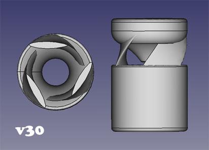
Similar to v30 but the top of the reducer has no radius and the ribs are now rotated a bit more. This extra rotation has added to the flame stability and air induction. Previous versions which could support the 030 mig tip were at the low border of neutral flame. This guy accomplishes a good neutral flame at 2 - 15 psi with the 1.25 inch nozzle.
-
How large are those ports? They seem big by my eye gauge.
I suspect it is burning in the plenum. That fourth image looks like it is still running? The last image looks like the flame is burning right after the injector.
-
I have printed and tested v31 and v32.
V31 induces more air and has better mixing then v30. V32 did not perform as well. It produces a large secondary flame.
The changes in the flame are all small lately. I have to pay extra attention to see them. I played with jet position while paying closer attention and have found that a 1/4" back from the throat is the best position in several version. This is much deeper into the reducer then I had been positioning it usually.
-
The jet position is flexible. I have positioned it directly in the throat and all the way back at the mount block. Between 1/4" behind the throat and 1/4" behind the end of the reducer, it is hard to discern much difference in induction. I usually position it around where the ribs and the reducer meet.
I just noticed the aerospike versions induction curves are much better than the rest.
-
I was a bad scientist and I changed more then one thing at a time. I will go back and print each thing in it's turn but I had an idea and went with it.
I have enough versions now that the version system I came up with is no longer entertaining so I counted the versions and will be adding them linearly from now on.
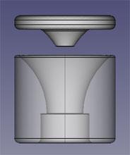
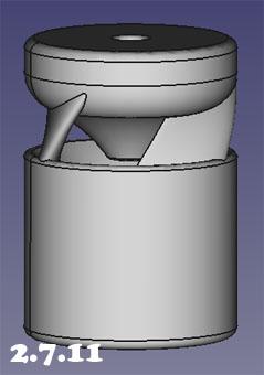
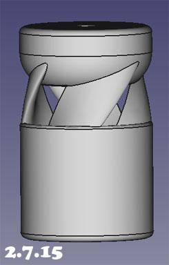
Here is the new golden boy:
He is version 2.7.11 with some changes:
- The ribs have been lengthened to 1/2 inch (from less then 3/8)
- The airfoil has been changed to a laminar profile
- The inlet to rib ratio has been bumped to 60/40 (from 50/50)
This burner induces the most air of the bunch. The flame has visible rotation like 2.7.11 but without the instability I was seeing.
Now I am printing versions with one change at a time, like I should have, to see what each change brings. V31 is the same but the inlet to rib ratio is back to 50/50. I also intend on removing the small radius at the top of the reducer to see what a sharp edge does there.
-
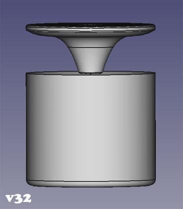
The first image of the small flame is below 1 psi. The aerospike really moves the air.
I tried to create a semi match of the reducer shape in the spike.
Now I want to play with lengthening the ribs a little bit as they were so short the first time around. See if it hurts or helps.
I have also modelled what I thought Frosty might have been saying. A thin disc with a smaller spike.
I look forward to seeing what a high rotation flame will do when the burner is put into a forge.
When you say fins in the nozzle, are you thinking straight fins or something opposing the flame rotation?
-
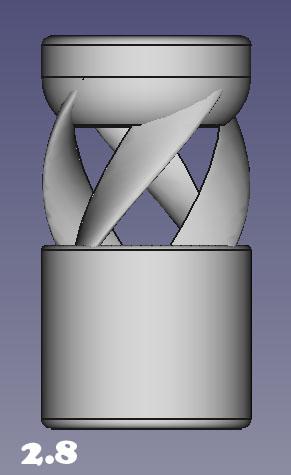
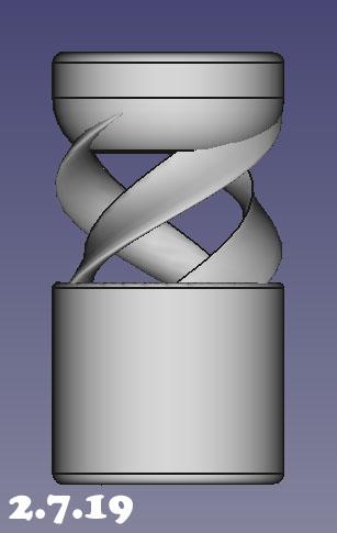
I tinkered a bit more. I played with 2.7.11, 2.7.15, and 2.7.19.
I gave bad data when it comes to 2.7.11 which is the aerospike version. With the shortest ribs of the bunch, it induces around the same amount of air as golden boy 2.7.8. It is partly unstable at start up. It has visible high speed rotation in the flame. The rotation causes the flame to come out in a cylinder. The flame is impossible to blow out with my lungs. I can blow out all other versions. It is a weird flame, it seems to oscillate. I also noticed during the smoke tests that the smoke which rolls in from the side of the ribs forms it's own small vortex on it's way to join the main vortex. I definitely want to play with the aerospike a bit more.
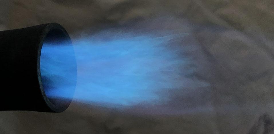
Here is a low pressure flame in the 1.25" nozzle with the 030 mig tip:
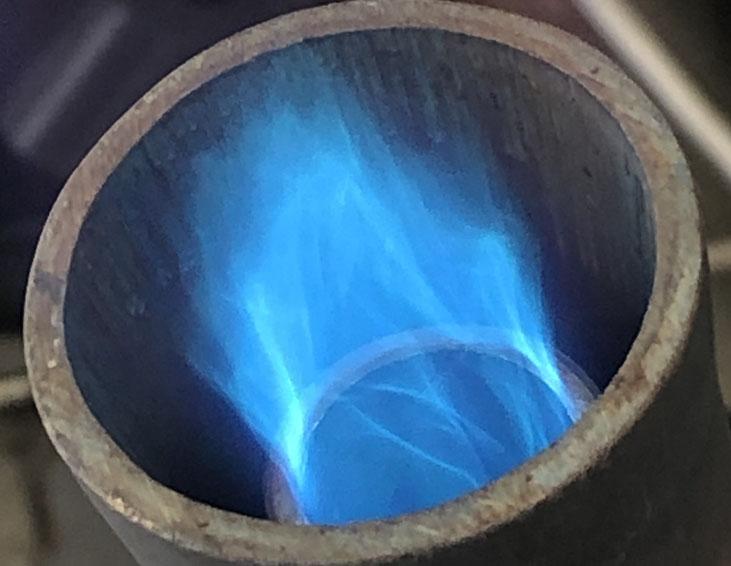
Here is a 5 psi flame with the 030 jet:
Here is a short video to show the small smoke vortex:
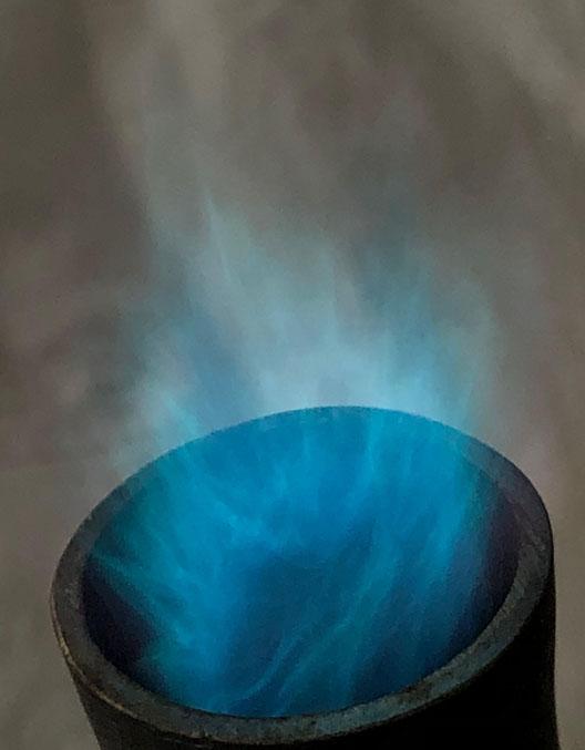
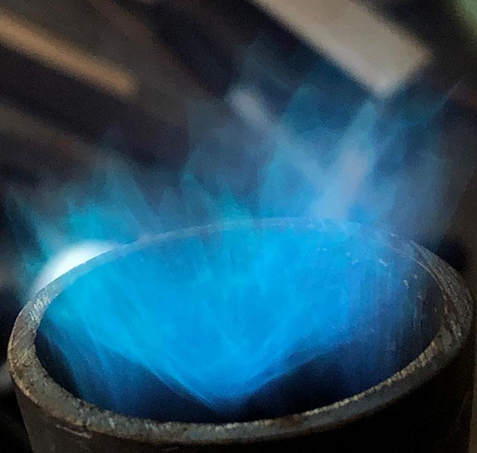
2.7.15 which has the 4 ribs which were short produces the greatest vortex. It is visible in the flame. The reduced air inlet area causes the induction air to rush in but it reduces induction volume. Here is the best image I could get which sort of shows the rotation. This is with the 023 jet:
I also played with 2.7.19 which has the extra twisted ribs. It induces better vortex then 2.7.8 without decreasing induction air like 2.7.15. I may play with more twist a bit more. Unfortunately I broke it when switching out mig tips.
-
1 hour ago, Frosty said:
Where do you think your parents went wrong?
I think part of it is that when I asked why, they pointed me in the direction of the answer.
My daughter is home schooled. I wanted her to graduate thinking that learning is a great thing. I sure didn't learn that in school. I think we are born scientists, curious about the world around us. Unfortunately, that goes extinct in some people. With my daughter, we encourage it and get out of the way. On a regular basis, she becomes the teacher.
Who knew you could learn so much from mouse trap catapults, water rockets, and paper airplanes?
51 minutes ago, Mikey98118 said:If you you include the ribs-as- airfoils idea by turning the end cap into a hub and wheel structure...
Are you meaning draw air in from the back with a fan looking assembly?
-
41 minutes ago, Frosty said:
Hoping it increases the general befuddlement, a boy has to have a hobby.
As stated by someone somewhere else recently, a good rabbit hole can be fun. I will be playing with the dual vortex on the side just because it's cool. I still happen to think the tornado in coke bottles is cool though. Luckily I have a daughter to give me a reason to build those again. I even get to call it teaching.
I enjoy working within the confines of naturally aspirated. We could add energy and do a lot of cool things, but working only with the potential energy of the fuel is challenging and entertaining.
-
Matt Watson: What is the intended goal of your idea? I think it's a case of "There is no free lunch." Your idea would require energy and would be a partial blockage of the mix tube. It takes very little blockage to severely reduce air induction. Also, 3d printed, there would be enough friction, it probably wouldn't rotate with just FAM flow.
Mikey suggested fins inside the mix tube but they would be intended to purposefully remove some energy if we had a vortex which was too strong at the flame end.
Any time I try to aggressively control anything, it is more harmful then helpful to performance. The best performance has been when the geometries go with the flow. All shapes are designed to cause as minimal drag as possible while encouraging flows to move how we want them too. Doing any more takes energy which reduces induction.
You say you are new to this and learning as much as you can, read Burners 101. It is long and there is a lot of information, take your time. I have read it twice and learned from it, both reads. If after that, you are still hungry, read the T burner thread, Mikey's book, Ron Reil's pages, Zoeller's pages, the Hybrid Burner pages, and Wayne Coe's pdf's. There is a lot of information out there. Just remember that some of it is aged.
Frosty: Even crude hand drawings with a good explanation, will work. Nothing too crude though, I don't want you to get moderated.

I don't think I am creating the very cool dual vortex. I think the short ribs and lack head room cause the streams to flow through so fast that it is almost linear flow. I will play with it a little more with smoke and really pay attention. I saw a severe drop in air induction so I didn't play with it much.
I am pretty sure I have a good picture of the airfoil you describe. I understood how lift works with wings but when it came to burners, I didn't know if or how any of it would help. I took the safe approach and went symmetric. Increasing the outside velocity makes sense. The four rib model with smaller air openings absolutely increased vortex because it increased the induction velocities but at a cost of induction volume. Here, a drawing would be great so I can get it right. Definitely worth a shot.
With the vortex, the stronger it is, the more the air is induced at a lower angle of attack. The streams line up. Said backwards, the weaker the vortex, the more likely the air is to come in around the ribs from all angles. Some of it, at the centers of the inlets, induces straight in towards the accelerator. If we get the outside air streams to higher velocities, it naturally changes the direction of the straight induced air into the inside of the next rib. That was a stumble of words, did that make sense?
-
19 hours ago, Frosty said:
It's really hard to sit here and watch
Each print costs less then $1. If you can explain things clearly or put up drawings of your ideas, I will CAD/print them and report.
19 hours ago, Frosty said:This is all just so wicked cool.
Agreed. It is hard not to be enthusiastic about how cool it is. I drive my wife crazy routinely.
19 hours ago, Frosty said:I'm thinking the thick cap with the rounded inside edge could be flat and thin instead. Have you taken note of how the smoke behaves near the cap?
I think it could be thinner as well. I originally made it thick so that the jet would be axially aligned and so the choke had a good flat to seal against. I don't think much length is required for either purpose. The smoke rolls down the radius and into the back of the vortex. It seems smooth flowing. Are you thinking skip the radius and have a thin flat disc instead?
19 hours ago, Frosty said:The aerospike structure didn't work and my intuition says it should have been beneficial. Now I'm wondering if anything in that area is a good thing.
I have not been fair to the aerospike yet. The ribs were too short on that model and I suspect the spike too large. The spike ended where the reducer began so the mig tip barely came out of it. I was thinking it would kill dead airspace up by the accelerator. Instead it causes the streams to flow in and straight down the mix tube. More forward push. It doesn't induce as much air but it's output velocities seem higher. I had already created another version which has a thinner disc with much smaller spike. Part of the spike will be the jet itself.
You were right about the four rib version. For the most part, there isn't much change at all. I think it may induce a little more vortex and a little less air but, if so, it is small enough that it is hard to tell. Version 2.7.8 is still the golden boy. Changes are variations of him at this point. I still haven't printed 2.7.19 with the extra twist yet.
You were also right about the 030 mig tip. Version 2.7.8 runs neutral from 1 to 10 psi with the stepped/flared nozzle. Above that, it begins to go purple. A 1.25 inch diameter flame at 1 psi is pretty awesome. If I put the smaller nozzles on it, it can be run on the peg still. I tried the 035 but that was too much. I got a neutral flame above 15 psi, a bit much. I think the 030 is a good balance.
15 hours ago, Mikey98118 said:Intuition tells me that you need thin edges on the outer edge of the ribs
I was wondering about this one. Originally I went with a standard symmetric teardrop airfoil. I will be playing with airfoil shapes. If you describe it and think it might be a good idea, I will try it.
-
I'm on the same page. I have not lost sight of the burners purpose. I was just tinkering with vortex as I wait for bigger jets. I was trying to see how much is too much, why, and how to get there.
-
The 2.7.11 fins are too short, shorter then 1/2 inch. I took 2.7.9 and made versions with 1/2, 3/4, and 1 inch length ribs. The 1 inch ribs induce more air and more vortex.
I suspected when printing the more extreme ribs that they would be poor performers. I agree that brute force can do nothing here. Now I am trying to learn what the vortex wants so I can feed it properly. Make him happy to exist. In the smoke tests, 2.7.15 has the strongest vortex. 2.7.8 has clearly visible vortex with smoke but he also induces much more air.
2 hours ago, Frosty said:I'd be looking at low aspect wing profiles. The bottom surface maybe almost flat and the upper surface only exaggerating the line of the cord from leading to trailing edge. The slant you're putting on the fins looks like a delta wing. Reversing it did exactly what reversing the sweep or camber does for combat aircraft, made it more unstable. Controlled instability is what makes combat aircraft maneuverable. A burner needs a smooth FAM stream. Yes?
I will have to think about this and research to fully understand.
I have played with many rib profiles and 2.7.2 has been the most successful. When monitoring smoke, it flows around 2.7.2 ribs without turbulence that I can see. I intend on small changes to it soon.
I have a few more big changes to try first. I am still playing with the extra rib but bringing the rib/inlet ratio to 50/50. I am also making the rib length 1 inch.
I am also playing with 3 ribs with the 2.7.2 rib profile but decreasing the helix pitch length to see if it hurts or helps.
I have not printed either yet.
-
All of these burners have a sliding choke on them. As you said, mostly as a safety measure. I do partially close the air inlets once in a while to tinker but usually they are wide open.
I have enough vortex that I think it needs to be toned down but you think I am on the right path. You have previously stated the more the better. What is your thinking on that? Is there a limit? What is the end goal with your vortex burners?
-
Frosty: I have written a few responses and deleted them. I got nothing. Your wordcraft is strong.
I am still awaiting mig tips so I have been playing with dynamics. I have been focused on more power to the vortex. Most of the experiments were flops.
I tried a cone drop shape on the accelerator block. This caused less vortex and more push.
I tried curved airfoil ribs. First in similar dimensions. Then in a constricting pattern. Then in a very aggressive angle. All versions induced less air. The similar dimensioned curved ribs showed turbulence in their curved section with smoke. The constricting pattern blocked too much air. The aggressive angle got in the way of the vortex I think.
Then some vortex success with another rib.
More powerful vortex. Too much. It comes out the pipe rotating very fast and spreads. If the pressure is higher, the center of the flame is void and a full rotation can be seen in the flame. It is louder and has a scattered secondary flame. It induces less but I did not change the length of the ribs to keep the 50/50 ratio. If a longer mix tube is used to calm the rotation, it doesn't induce as much. Mesmerizing to watch the flame. Here is a low pressure shot:
In my playing, I discovered that 2.7.8 which has 1 inch long ribs does better then 2.7.9 with 1/2 inch long ribs. I am now printing a version with 3/4 inch long ribs. I am up to 2.7.17 with all the vortex play and 2.7.8 is still holding it's place. It induces a lot of air, it forms a good vortex in the inducer, it mixes well, it has good range, and it can do all of this at very low input pressures. Now we'll see what that does with a bigger jet.
-
I see a mig tip that is too far back and a choke that is partially closed.
-
What is the final inside volume of that forge going to be?
-
1 hour ago, Lee Wehr said:
Nice to know I made a one off design.
The downside to your own design is that you have to design it. In order to get it working well you have to understand the science happening there, trial and error your way to a working burner, get lucky, or a combination of that.
6 minutes ago, Lee Wehr said:I have some more pipe. Back to the drawing board!
I recommend you look into the Mikey burner since you are replacing the tube anyway. Then there is no designing needed. Build it to the recommended specs, tune it, and it works. His design is similar to what you built so the build would be similar.
What is this burner's intended purpose? I am just curious because of it's 1 inch size.
-
That burner is a side arm burner. The best I have seen for side arm are the modified side arm or the z burner. Both use a larger fitting then the mix tube size for increased air inlets. Even still, if you follow the link to the z burner page, you will see a rich flame. A Frosty T produces a better flame with similar fittings.
You might try an 023 mig tip, it seems trivial but it makes a difference.
-
As far as design, the air inlet holes remind me of a Dave Hammer burner and the jet mount system reminds me of a Mikey burner but this burner is a Lee Wehr design.
Unless your fuel pressure was lower then you are going to be using normally, the flames visible in the air inlets should be concerning. A choke is used to reduce air induction, not to prevent flames from sucking back. As is, that first image shows a very rich flame which requires more air. The .045 mig tip would make this worse.
Be very mindful of carbon monoxide. We all should always, but rich running burners produce more. It is a stealthy danger so adequate attention and ventilation always.
Those air inlets are quite forward, towards the flame end, then usual. Typically they are as far back, towards the gas jet end, on the pipe as they can be.
Where does the gas jet end in the 1" pipe? I suspect it is quite a ways back behind the air inlets.
3D printed plastic burner experiments (photo heavy)
in Gas Forges
Posted
I'm glad someone else likes these burners too. My wife can only look at so many plastic burners, which look the same, before even the pretend enthusiasm runs low.
I think they are getting close now. Most of my recent experiments decreased performance. I still have a few more things to try, then the next step will be a bit more effort towards the casting side.