
Another FrankenBurner
-
Posts
625 -
Joined
-
Last visited
Content Type
Profiles
Forums
Articles
Gallery
Downloads
Events
Posts posted by Another FrankenBurner
-
-
Thanks for the clarification Mikey. I have been studying vortices lately. I also borrowed my grandfather's copy of Basic Science for Aerospace Vehicles by Northrop Institute of Technology and have been reading about airfoils, turbulent and laminar flows, drag, boundary layers, skin friction, etc. I have a handful of idea's to play with. My latest experiments have all been geared towards a more powerful vortex.
-
1 hour ago, Mikey98118 said:
Thre is no argument, unless we cause one...
My intention was not to argue. I am not the arguing type. If a discussion has devolved into an argument, it is no longer constructive. When I do question or disagree with a statement, my reasoning for discussing is to educate myself. I have no convictions in any of this. I'm just the curious type and question everything, trying to get to the whys of things.
-
I was under the impression that flame holding was the original reason that flared nozzles were added to homebrew burners. Ron described making solid fuel fires inside a forge, which used aussie burners, until the forge got to autoignition temperatures, so the flame would not be blown out.
Isn't having an increase in volume after a straight mix tube important? Whether that be a forge or nozzle of some sort.
I am able to maintain a clean flame out the mix tube sans nozzle but it's btu output is low and the mix tube velocity is critical. Too high and I get blow off, too low and I get suck back. This range is pretty small. If I want for higher output, I have to move more volume. The only ways I can think of doing that are higher velocities, larger geometries or a combination of both in the case of a nozzle.
-
Mikey: I reread principles material on vortex burners and think maybe I am understanding a little better. The intent is to create a fast moving vortex so that more air can be induced without providing additional push/pressure. Instead of focusing on how much air I can induce, I should be focusing on creating as strong a vortex as possible, as it will induce all the air needed along with a host of other benefits. Do I have that right?
In the latest burners 101 post about burner dynamics, you mention both spin and vortical flow, could you elaborate on the difference? I am thinking spin is air spinning down the outside of the mix tube where as vortical flow is a fast moving cyclone down the center of the mix tube. Do I understand that correctly?
If so, is there anything I should change to attempt more votical flow?
Frosty: I was just thinking of how to make a tapered tube. I will not change more then one thing at a time. I am confused enough without making it worse. Especially when Mikey comes in with a mental curve ball.
For smoke, I rolled a piece of paper towel tightly and let it flame until an ember. I created a small ember to see a small piece of the stream and a long one to see it flow around the ribs and such. I learned a bit about what is going on in there. I have some video's but I have to see if any are good. Between lighting, holding the camera, holding the smoke, and remembering there was a hot flame at the one end, I suspect the video's are fairly poor. If so, I may try to pull out a few stills.
-
5 hours ago, Mikey98118 said:
How much air is induced is mainly a question of jet orifice diameter to mixing tube diameter. Induction is also effected by mixing tube length, which substracts from the amount of induction the longer the mixing tube is, by friction. Induction is also effected by the diameter of the flame retention nozzle, which adds induction to a smaller amount than mixing tube friction subtracts from it.
I think I am misunderstanding, are you saying that the main factor to amount of air volume induced is the jet orifice diameter to mix tube diameter ratio?
With the same mix tube and jet diameter I have printed inducers which vary the air induction widely, depending on their design, so I am confused as well.
I induced smoke into a few of the versions. It induced straight in until it entered the fast moving cyclone inside the inducer. The closer to the throat, the tighter and faster the cyclone. Now I just need Frosty's smoke pressurizer. I also want to play with the aquarium and food coloring. Fun to actually see something instead of imagine it.
I also played with the 3/8 burner some more. I am able to induce enough air to have a neutral flame at 5 psi. It's btu minimum is higher then the 1/2 inch. I have a piece of fire suppressant pipe which is also 3/8 pipe but the ID is larger. It runs neutral at 3 psi. Amazing how small of changes in dimension make such big changes in flame.
1 hour ago, Frosty said:I was jonesing for full length taper mixing tubes like the old days.
I am trying to figure that one out as well.
-
I could try to print jets. My print quality would leave a bore which causes turbulence. I might be able to print small and use letter bits to open it up. Fun idea.
A burner head with a taper after the throat lengthens the head which I imagine decreases the required diameter so it is a trade off. The big challenge I have been up against is that it also means the mix tube length is shorter which is no good when the head is plastic.
-
I suppose it is all a balance choice. For practicality, a longer mix tube and/or larger stepped nozzle would be comparable to moving up to the next ID mix tube with the same jet. So long as the low end range of the next size is low enough, it's easier to build. I still see the practicality of the 3/8 burner but see why you state that it requires moving on to needle stock or capillary tubes.
I have been thinking about the dynamics of each piece with my experiments. Trying to learn what they all do.
With the trumpet length, if the diameter is unchanged, I suspect that shortening the trumpet induces more spin and less air and vice versa when lengthening it. I suspect that increasing the diameter increases both, spin and air induction.
I am starting to understand the relationship between mix tube diameter, jet diameter, and output desired. It has more to do with mix tube velocity vs btu's and less to do with induction than I originally thought.
I'm still not entirely sure how mix tube length works. I feel it is the balance measurement I know the least about. Longer mixes better, lowers velocity, and reduces air induction. Right now I trial and error with a range of lengths but the best balance usually falls close to the 8-9 rule of thumb.
I will continue playing with a smaller throat with a taper out like in version 3.3. It makes the heads longer but I am curious if there are any benefits.
After learning what all this stuff does, finding a balance between inducing enough air, adding good spin, mixing properly, and not being overly large while being stable over a good range, will be the next step. This balance can be shifted depending on application requirements.
With all the fun talk over in the NARB thread, I am wanting to jump on that bandwagon as well. So many exciting projects. I better finish the inducer learning first.
-
I suspected that would be the case when I printed the 3/8 burner. As I am waiting for larger mig tips to try in the 1/2 inch burner, I figured why not give it a shot. I was hoping that since I might be able to upsize the mig tip in the 1/2 inch, just maybe I could pull off a mig tip with a 3/8. I am toying with increasing the diameter and length of the reduction in an attempt to induce even more air. Mostly to learn about the limits. Fun experiment and challenge. I imagine even if I did pull off inducing enough air, the volume would be great enough, the FAM velocity down the mix tube would be very high.
As is, with the 1/2" burner, I am anxiously awaiting the mig tips. I am curious what the change did to the induction curve. I would rather have better range without fiddling with a choke then absolute maximums. Though, I want to find the maximums I can achieve so that I can understand the hows (and maybe the whys) and detune from there if needed.
With the turn down range of the 1/2" burner, I suspect it will work well in a small forge. After seeing AngryDaddyBird's first forge, I am building a coffee can forge to test.
-
I will do some smoke tests since I am waiting for mig tips at this point. Also since I am waiting, I scaled and printed a 3/8 version of 2.7.9 to see if it could induce enough air with an 0.023 mig tip but I have to make mix tubes and proper nozzles. I stuffed a 3/8 nipple into it and faked some nozzles and it runs rich. I haven't given it much of an attempt yet.
-
Do you have any pictures of it running that you could post?
-
If your main goal is fuel savings, there a lots of ways to accomplish that. Several have nothing to do with your insulating choices.
The insulating properties of the kaowool win over all the castables and bricks for insulation value and lack of mass. The downside is that it is fragile and when heated, breaks down and creates hazards you don't want to be breathing. Usually 2 inches is recommended. There has been recent discussion about 1 inch being enough and also some talking about trying 3 inches. With 2 inches, I can hold my hand on the shell of my forge for a few seconds after it has run for hours. Three inches might provide some savings but I wouldn't expect it to be much.
The reradiating coatings (like ITC) are used to increase internal temperatures inside the forge. The coating absorbs energy, becomes very hot, and radiates that energy to heat your work. ITC is a poor choice in that it breaks down quickly in the forge environment and is expensive. People are happy with Metrikote and Plistix which serve a similar function. A thin coat is better then a thick one.
You could put the coating directly on the rigidized blanket. This would prevent the hazardous breathing situation and produce a forge which heats very quickly to highest temperatures. The walls are fragile to bumps. If you are clumsy with metal placing, it might break through and require patching.
This is where kastolite comes into play. It is tough at high temperatures. It is somewhat insulative but it is also mass. This is added to toughen the walls at a cost of fuel efficiency, heat up time, and maximum temperature. The thinner you can get away with, and still armor properly, the better.
There is one caveat though, these rules of thumb are if you are a typical hobbyist user. If this forge is to be heavy used, with lots of metal through it quickly, and it is not shut off often, more mass can be helpful in stabilizing temperatures.
A general recommendation which several have reported happy results with:
- 2 inches of rigidized kaowool
- 1/4 - 1/2 inch of kastolite 30
- thin coating of Metrikote or Plistix
Your shell is very large, you could fill in the extra volume with rigidized perlite. Mikey had recently talked about it in Forges 101. I have never tried it though.
Other ways to save fuel:
- Better burner design (Ron doesn't use Reil Burners anymore)
- Proper baffle walls
- An idle circuit (big savings for me)
As to forge shape, I have never built a forge with square corners but Mikey is usually advising against them. He tends to uptalk the oval shape quite often. Square corners do bad things to flow dynamics. With your current shell, if you suspended the blanket with perlite, you could roll the blanket to create a more rounded interior. The next big question you should be asking is how are you mounting the burner in what position. Square forges tend to have the TDC mounted burners which Mikey also advises against.
This is not intended to be discouraging at all. Hopefully any of it is helpful in getting you to a hotter forge.
-
Frosty also said the ITC100 won't last, in his post. It is not designed for this and it flakes off quickly. Wayne Coe sells Metrikote and Plistix and Larry Zoeller sells Plistix. Both options are better options for the hot face.
On the kastolite, it is recommended not to over kill it. It is used to armor the walls against clumsy hands hitting the walls with the metal and to cover the fragile hazardous blanket from the flame. Add enough to be protective but no more. As you add more, the forge requires more fuel to heat, it takes longer to preheat/cool down, and it can reduce the maximum temperature it can reach. I have seen recommendations between 1/4 - 1/2 thick layers. I use 3/16 inch currently and it is tough enough for the occasional bump but I am careful when placing my iron in the forge.
-
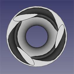
Frosty: Here is a shot from the top to hopefully explain the ribs. I mostly have no clue what I am doing so at one point I looked into airfoil design in an attempt to streamline.
I have ordered 0.030, 0.035, and 0.045 mig tips. I will take your advice and not get out the tip cleaners until I have an upper bracket. I am expecting the 0.030 to be over sized. It would be nice if I am wrong.
HojPoj: That is a fun idea. Bigger selection in sizing, super cheap, and listed by their actual diameter. Wouldn't that be nice. Like you, I suspect the turbulence/spread makes them poor performers. I have seen a few posts in which people had drilled out their own jet, left the length short, and it didn't work well. Cheap enough to play around with anyway.
-
I tested another version today. Major changes to the flame. I took the trumpet restriction and doubled it's length.
This change increased air induction by a magnitude. With the 0.023 mig tip it is producing an oxidizing flame with the pressure needle resting on the minimum peg. I ran it with another tip, an 0.025 which has been drilled to 0.032 actual. It also produces an oxidizing flame. It's low pressure range is the best I have produced.
I am going to use torch tip cleaners to enlarge the jet. I also ordered some 0.030 mig tips to see if it can support that large.
-
Sorry for the confusing post. I promise it sounded legible in my head when I wrote it.

As to specific terms, I can use whatever anyone likes. I generally try to adapt to the terms being used in the discussion. I am mostly just going to lurk until I have built a couple so I am not just another guy talking without knowledge.
It's a fun topic.
-
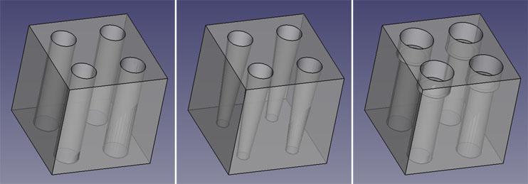
If you are asking me, I am talking about the shape of the ports. Usually ports are just straight cylinder voids left by removing crayons. I am talking about either a taper, a partial taper, or a step of some kind.
Here is a quick rough CAD of what I mean (tops being the flame face):
-
8 hours ago, Frosty said:
Actually the prime functin of a flared nozzle on a home made burner is to increase induction, reducing flame velocity is good being a flame holder is a happy extra.
Increasing induction was part of my mental picture of tapered ports in a NARB. Less back pressure and more throughput, allowing lower pressures to move more air for cooling and cleaner burning while giving us the flame holding characteristics. Tapers slow the stream as they increase in area/volume. If looked at backwards, the further upstream you go, the higher the velocity of the FAM. This may provide a natural brake to flame propagation backwards.
I am basing all this thought on my experiments with tube burners. When using a tapered nozzle, as the fuel pressure is decreased, the flame rolls back into the nozzle further wherever the propagation velocity and the FAM velocity match. It gives the burner a larger range of operation.
As long as the velocity at narrow end of the taper is higher then the propagation velocity, the flame will not flash back into the plenum.
The major downside and possible idea killer is the fact that as the flames move back into the block, they heat the block more/faster. In tube burners, I have run higher end orange nozzles without flash back but with more ports giving more surface area to heat the flow, it may make the problem worse.
One possible solution to this could be to use straight ports and have the tapers only make up a portion of the length. Another thing to balance.
I had previously mentioned a shoulder or stepped nozzles right at the outlets of straight ports. Is this what you mean by a bell section? I didn't clearly follow. I think this would be more resistant than tapers as are stepped nozzles on tube burners vs tapered. They require higher input velocities and the amount of step and overhang are more critical then a tapered nozzle. The upside I can envision is that the flame would not roll back into the burner block beyond the steps unless it flashes to the plenum.
Another possible solution. If the ports are closer together, the block has less mass and less hot face with the same amount of cooling. It isn't as convenient for spreading the heat to a wider area. This may be why the Giberson burner heads have ports which are so concentrated. It also makes it easier to balance flow distribution among the ports.
Having more ports which are smaller provides a similar solution. Less mass, more through flow.
If we are getting crazy, striving for perfection, we could think about making the ports on the outside of the header different diameters then the inside ports to balance the flow across them. Thinking about the logistics of using shaped ports of differing diameters to get the header flow balanced while getting the entire throughput balanced with the induction device, makes my head hurt.
This is the greatness of 3D printing, if we actually figured this out, we could easily print a mold which matches all this. I envision lots of experiments on the horizon. Maybe in plaster or hydrocal. Something cheaper then kast o lite.
Inducing enough air at lower velocities and still having enough energy to mix it all and spread it evenly across a plenum is quite a chore.
As far as I am concerned, the Frosty NARB is "good enough." Wide range and it makes metal hot. Thinking and tinkering are just part of the fun.
-
My thinking on the tapers, I'm not sure if they are accurate. Balance the size and count of the ports so that the Fuel/Air Mix(FAM) velocity is beyond the propagation velocity right at the outlet. When the propagation velocity increases due to a heated block, the flame will move back to a tighter area of the taper where the FAM velocity is faster and matches the propagation velocity. A downside to this is that the flames would be deeper into the block to heat it more/faster. I am not sure if it could be balanced to prevent blow back or if it would just make the problem worse.
-
I should have specified, I have no idea about that recipe and was not suggesting it. I was just sharing it. The Potter's Center said they have used it as a kiln wash and it flakes similar to ITC. They said it is cheaper for reapplication and it is tougher then ITC. They mentioned using it in a throat arch as it could take a beating.
-
That clears it up. I did not understand how zircon worked, just what it did for us. Understanding that it is a poor conductor explains the how. Thank you sir.
I'll have to pick up a bag of zircon flour so I can play with it. Which reminds me, I was at the local Potter's Center, chatting them up about all this kind of stuff and he gave me an "ITC replacement formula" they had. He didn't know where the recipe came from.
By weight:
- 2 parts Alumina Hydrate
- 2 parts 35 mesh Kyanite
- 2 parts Zirconium (Zircopax, Opex)
- 1 part Vee gum T or Bentonite
-
An idea I had been rolling around to prevent blow back, use more smaller ports. It's less convenient to make but it would provide more cooling to the block. The block could also be shorter to maintain laminar flow which would mean less mass to cool.
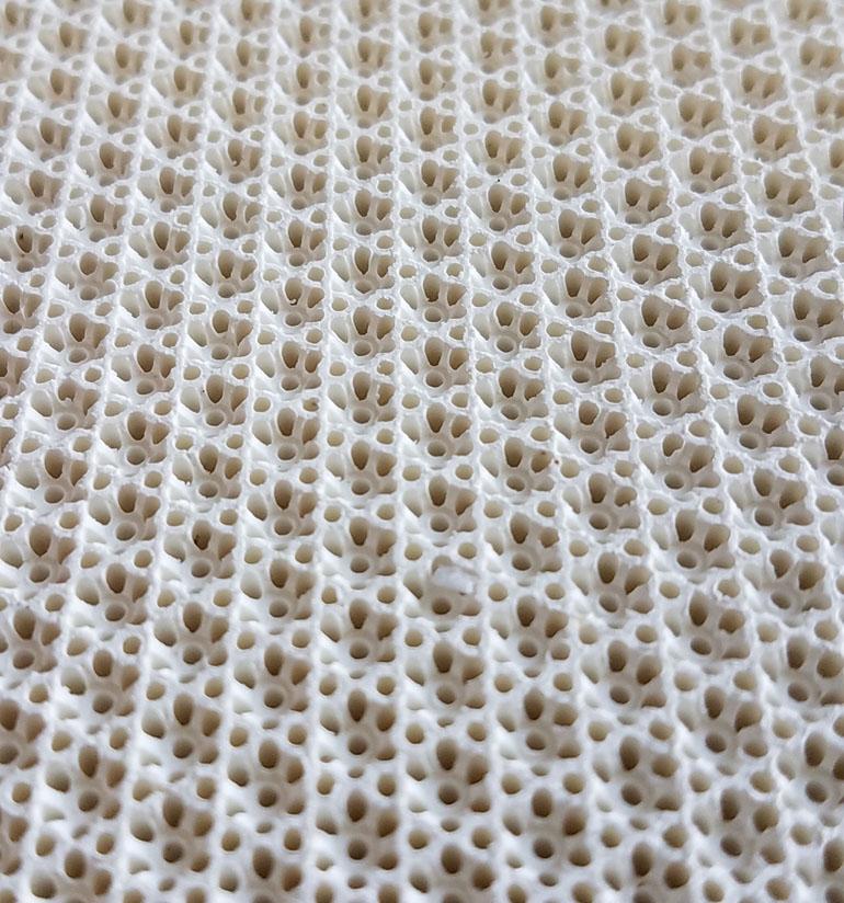
I have seen commercial NARBs which purposefully run the block hot for infrared heat transfer. They run a large orifice at a little over 1/10 psi through a stamped venturi without blow back. All of the commercial versions which I have dealt with have lots of very small ports. Here is a picture of the plate in one of them, it is 1/2 inch thick:

I don't know if what I am thinking is viable so I wasn't going to mention it until I had played with it a bit but you all were talking about plenum pops. I also don't know how more smaller holes vs less larger holes reacts to pressure changes etc. It seems as much a balancing act as the NA burner driving it.
My other thought was to 3D print a mold for the block which could add tapers or steps at the outlet to act as nozzles on each port.
A question for Frosty, I thought that the purpose of zircon was to absorb energy, become very hot, and radiate energy. If I have that right, wouldn't adding it to the face of the block cause the block to heat more because it has a hotter face? Or did I misunderstand the function of zircon and it would somehow provide a shield in this case?
-
It is rotating clockwise currently. That could be easily changed if you think we should try it. I printed a previous version in both directions and did not notice a difference in the flame aside from the direction it was rotating.
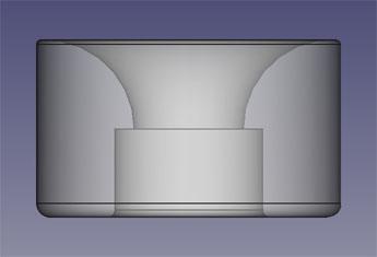
I plan on playing with diameter to determine the optimal diameter. Like with the experiments with the ribs, I will change nothing but the diameter for a few version to see how diameter changes affect the flame and what the maximum size is before it becomes a hindrance to performance. The only complication is the shape of the trumpet. To maintain the curve of the trumpet on larger diameters, that section will be longer. If it is not lengthened, the trumpet gets sharper which makes it more of a conical funnel.
The current trumpet is approx. 1.7 inch diameter, 1/2 inch long, and necks down to 0.622 inch throat diameter (1/2 inch pipe ID):
Originally my focus was on inducing enough air as this has been such a problem in the past with burner designs. The burner being printed with proper shapes makes it easy to induce too much air so it is no longer the focus. Now the focus is the cleanest burning flame over the largest range of pressures which is still stable. A few of the burners had a perfect flame at an exact pressure and were very picky about tuning. I had one burner which produced a purple flame but also had a large secondary flame which I took to mean improper mixing.
I am pretty happy with 2.7.2 so we will be working on casting him in aluminum for some actual forge testing.
We are also in the process of making another forge for these burners. This time using a cnc foam cutter to cut the inner profile for a mold for the kast o lite. I am attempting an oval split forge with burners angled upward from the bottom half. I am shooting for 350 cu. in. with more floor space. I took a 4.5 inch diameter circle, cut him in half, and split the halves by 3 inches. The forge is 12 inches long, my math came out to 352.8 cu. in.
When I am done tinkering with the induction portion of the burner, I will be 3D printing forms for a NARB to match the burner.
-
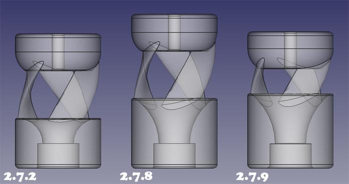
I was able to do some tinkering today. I had previous CAD and printed several iterations of the larger diameter burner with changes to the ribs only. The intent was to determine if the helix ribs are beneficial or harmful to burner function. Below are the burners tested against each other today.
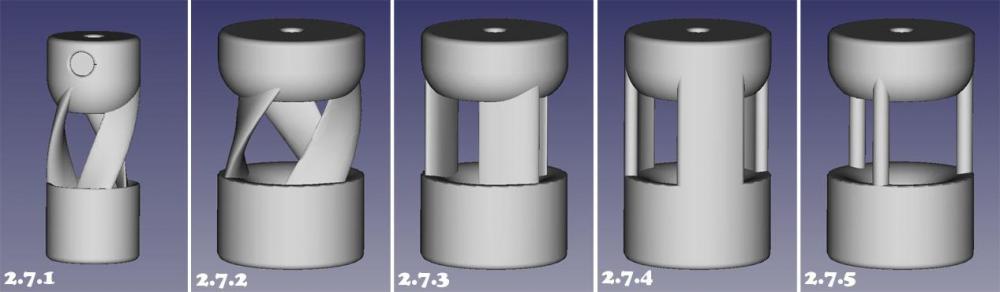
These are all 1/2 inch burners.
Diameter comparison: Going to the larger diameter is an improvement. Version 2.7.1 always has a small secondary flame, version 2.7.2 eliminates it for the most part. Version 2.7.1 can be turned down to 6 psi before it starts to stall and it is burning very poorly by then. It is happy above 8 psi. Version 2.7.2 will run below 1 psi but it begins to produce a secondary flame if under 2.5 psi. It is happy at 3 psi and above. Both are happy to run above 20 psi.
2.7.2: So far this guy is the winner. The helix ribs reduce some of the air induced but it is because it is using the energy to add extra spin down the mix tube. This makes a flame which appears stable and constant. It induces enough air so it doesn't create a problem. It is happy with a larger range of pressures without having secondary flame show up. It is much less susceptible to drafts then the other designs.
2.7.3: Ribs are straight with the same airfoil shape as 2.7.2. This design induced less air and produces a secondary flame unless at higher pressures. It was not tested long as it was a poor performer.
2.7.4: Ribs are straight, rounded. This design induces more air then 2.7.2. The flame is more turbulent and less stable. It has obvious signs of spin down the mix tube when looking at the secondary flame. The spin almost seems to oscillate or collapse which is what causes the stability issues. It has a fluctuating roar.
2.7.5: To see what would happen with maximum air opening. Going to the linear burner. It induces the most air of the bunch, at the lowest pressures. It has a secondary flame at most pressures. I guess it is poor at mixing.
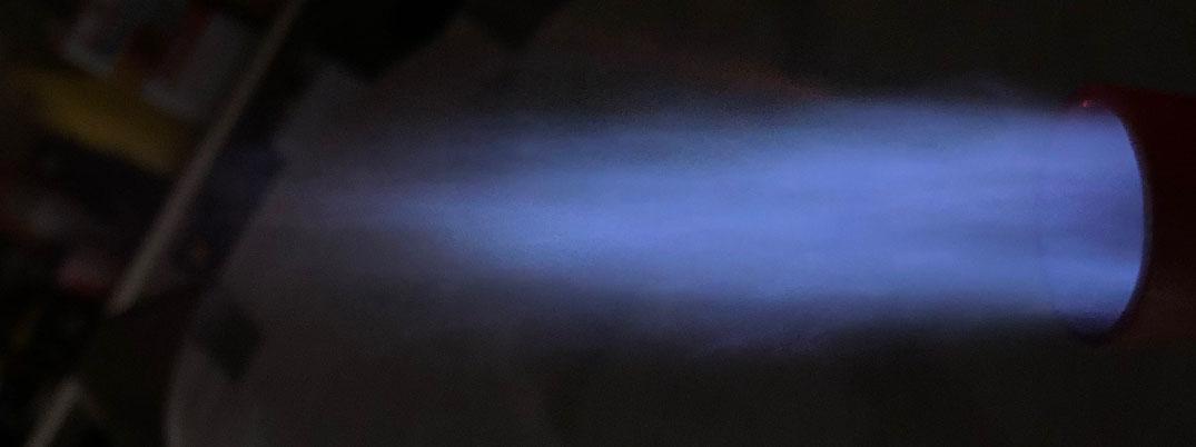
Here are some images of 2.7.2 flames at different pressures. I like it's wide accommodating range. Above 5 psi, it needs a bigger mig tip as it induces too much air. They were all taken shortly after startup to prevent orange in the flame from the nozzle.
Low flame, <1 psi, without a nozzle:
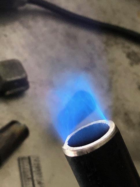
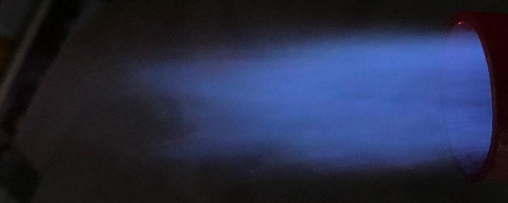
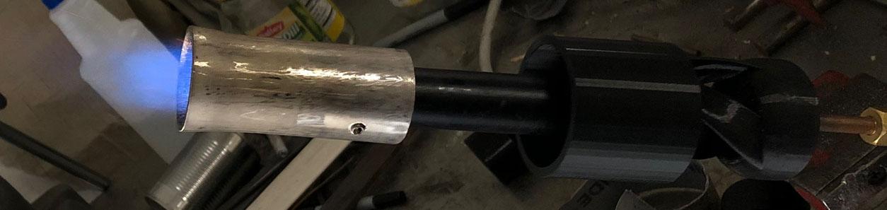
I had a burner flare from Larry Zoeller meant for a 3/4 inch burner. I made a step out of 3/4 pipe to the 1 inch stainless flare. This gives me a stepped nozzle which is also flared.
Here is a small flame at 3 psi:

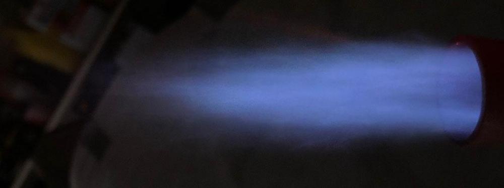
Here is a flame at 5 psi:
Here is one at 10 psi:
Now I am going to play with the length of the ribs as they are much longer then needed. I have 1 inch long air openings and based on playing with two chokes, I suspect it will be happy with 3/8 - 1/2 inch.
As always, any conversation, criticism, suggestion, idea, or education is welcome and wanted.
Bigger diameter is better, thank you Frosty, you were right. More spin down the mix tube is better, thank you Mikey, you were right.
-
I recommend giving the build_a_gas_forge.pdf over at Wayne Coe's website a read, as he uses a hinged design. He uses hinges on both sides as the hinge/latch. This allows him to knock out hinge pins on one side and open just one side or hinge pins on both sides and raise the whole top with fire bricks.


3D printed plastic burner experiments (photo heavy)
in Gas Forges
Posted
A nice little twist of my own. It's usually Frosty who likes the play around with words. Thanks Mikey.